The BarButtons (UC) are a prototype model of the BarButtons. They are mounted Under the Controls, hence UC.
There are a few steps involved in building a BarButtons (UC) controller:
Print the case
Download the 3MF file here: barbuttons-uc-v2.5.3mf
The best results are if you print the case with the flat side down and the lid with the top on the plate. This will result in quite a bit of support material, but the finish is nicer. I suggest to print in PETG for weather resistance and use a line height of 0,2mm or less and use minimum of 4 walls.
Get the components
You need these components
- 2 x 12mm non-locking push buttons. You can get them at Aliexpress or Tinytronics
- 1 x 12mm non-locking push button with led. You can get this at Aliexpress
- 1 x Althen 5-way joystick (HS1-5 or HS1-6). More info at althencontrols website. Note that Althen does not sell to individuals, but only to businesses. They are based in the Netherlands. Ruffy Controls also sells the HS1.
- 1 x Wemos LOLIN C3 Pico Arduino board. You can get this at AliExpress or Tinytronics.
- 1 x USB cable for power
- some UTP cable for soldering
- 2 x M3 screws (12,6mm length, 2,8mm width, philips head). Screws for case assembly – Available at aliexpress.
- 2 x M4 hex bolts of appropriate length (~40mm)
Flash the Arduino chip
You can flash the firmware on the Arduino using the web flasher.
Assemble the controller
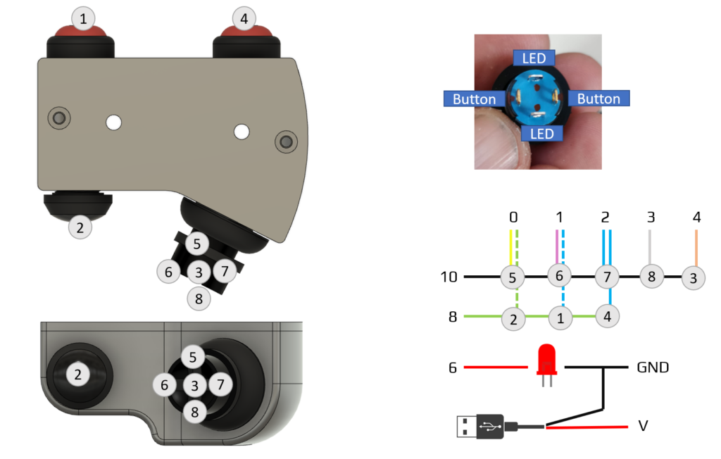
Review how to assemble the buttons and joystick in the case. The button with the LED should face the rider to show the operating mode of the controller. You probably want to keep it loose so you have some room for the soldering step
Solder the buttons to the arduino like in the diagram below. The colors from buttons connected to the joystick are present on the included cable. The wire connecting to pin 8 must be connected to button 1, 2 and 4, so you want to add 2 wires in some button terminals. The location of the led and button terminals of the button with the led is probably right, but check it before soldering.
Zip-tie the USB cable to ensure it is secure. Use some glue from a glue gun to fix and waterproof the USB cable. Use the M3 bolts to close the case with the lid.
Here are some pictures to illustrate:


Mounting the controller
You can mount the controller with some M4 bolts that fit through the case. You need to fabricate a bracket that sits under the controls.
Use it
You can find the user manual here.