This page describes the assembly of the BarButtons that ship with a PCB (March 2023 onwards). If you are looking for the assembly guide for the diy version, click here.
Contents of the kit
The kit ships with the following items:
- Case (front and back)
- 4 3x12mm screws to attach the front and back of the case
- Bracket kit with 2 m4 nuts and 2 x 25 mm m4 hex bolts
- 8 buttons, with washers and nuts
- Assembly tool to mount the button nuts
- Led assembly for indicator light
- USB cable
- Wemos Lolin ESP32 C3 Mini Arduino board plus header pins
- PCB to mount buttons and ESP32 board
- Velcro strap to attach the usb cable on the bike
- Tie-wraps to relief stress on the usb cable
- USB cable
- Optional shim kit of 5mm with 2 x 30mm m4 hex bolts

")


Nuts in case
Place the nuts on the recesses in the back of the case. Carefully tap the nuts into the recesses using a driver. If you choose to press the nuts in the case using the bolts, be very careful since it’s only M4.


USB cable
The USB cable provides power to the Arduino board.
- If the USB cable has a cloth shell, wrap some electrical tape around the cable to prevent it from expanding
- Carefully cut the outer shell approximately 7 centimeters and remove, exposing the 4 wires of the USB cable
- Cut the white and green wires since we don’t need them
- Strip the black and red wires
- !!! IMPORTANT !!! Check the polarity of the red and black wires. In some cases, the polarity of the wires was reversed (ie: the red one was ‘ground’ and the black one was ‘ plus’.
- Feed the USB cable through the hole in the case. If the hole is not large enough, drill it to the correct size or use a knife to do so
- Attach zip ties to the usb cable to relieve stress. Ensure that there is approximately 7 cm of cable in the case.
- Optionally, but recommended: Use hot glue to fix the usb cable in place on the inside of the case and make the hole waterproof.


")


Install LED
The LED is used to signal the state of the BarButtons.
To install the led, unscrew the nut and insert it into the front of the case. Ensure that the o-ring is between the led and the case. Insert the nut and tighten.


Install buttons
The buttons are installed in the front of the case
Note that the buttons have a fixed orientation so they fit the PCB. Note the flat side on the button and the case.
- Insert the buttons in the front of the case
- Add the washer
- Insert the locknut in the special tool on a flat surface, then screw it on the button and tighten. Be careful not to overtighten (!)
- Ensure that the pins of the buttons are aligned with the PCB and adjust carefully with pliers by rotating them if they are just out of alignment.
- Optionally: add hot glue to the nuts to prevent them from vibrating loose


Soldering
Next up is the soldering part! I’m personally not a big fan of soldering, but the kit makes life a bit easier because it comes with a printed circuit board (PCB) instead of wires. If you are looking for a good youtube video on soldering, I liked this one: https://www.youtube.com/watch?v=6rmErwU5E-k
Please ensure that the soldering connection between the header pins and the PCB and between the header pins and the Wemos C3 are good. Heat both the header pin and the pads enough that the solder flows between the header pins and the hole. See the pictures below for an example what a good connection should look like
- Cut the header pins so that you have a row of 3 and a row of 6 pins.
- Insert the header pins with the short end into the top of the PCB. (I use a bredboard for this to keep the pins in place, or alternatively you can pin them in a piece of cardboard)
- Solder the pins on the bottom of the PCB. Ensure that the connection is good and the solder flows well between the pins and the hole in the PCB.
- Insert the LED wires the top of the PCB and solder them tight from the bottom. The red wire goes to the LED_SIGNAL pad, and the black wire in the LED_GND pad.
- Insert the wires from the USB into the +5V and GND pads on the top of the PCB. Ensure that the +5V is the wire for plus (usually red, but sometimes black). Solder them from the bottom of the PCB
- Place the black circuit board on the pins of the buttons. The circles on the PCB should face the buttons.
- Solder the pins of the buttons to the black circuit board (16x). Ensure that the connection is good and the solder flows well between the pins of the buttons and the hole in the PCB. This requires quite a bit of solder. Note that the buttons are quite sensitive and limit the heat build-up in the buttons by keeping the time you touch the button pins with the soldering iron to the minimum. Aim for less than 2-3 seconds.
- Place the Wemos C3 mini board on the header pins, with the black ESP32 chip facing upwards. The header pins should be on VBUS, GND and 6 on one side, and 5,4,0,1,2,3 pins on the other side.
- Solder the header pins to the Wemos C3 mini (9x). Ensure that the connection is good and the solder flows well between the pins and the hole in the Wemos C3 mini.


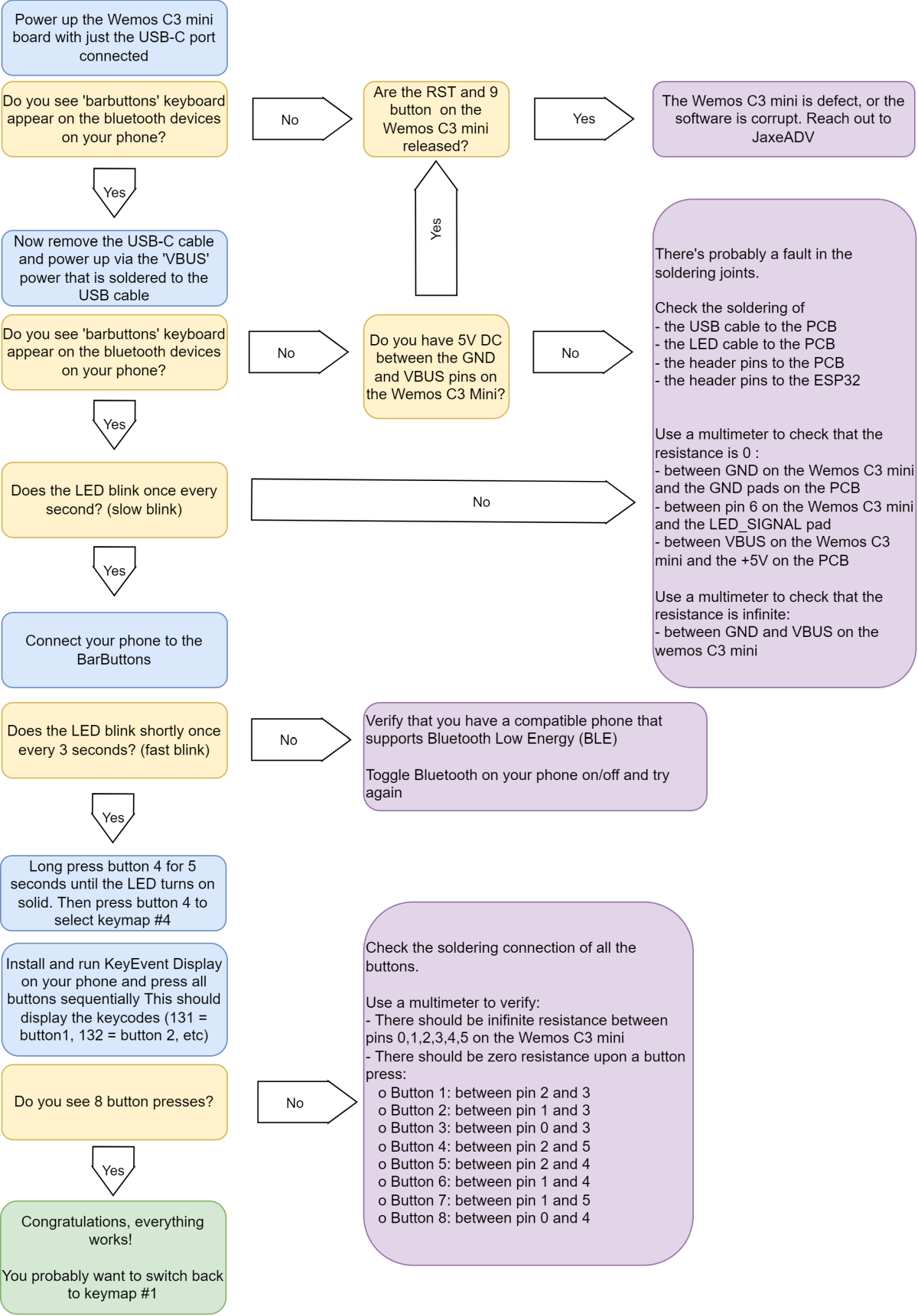
Verify that it all works
Use the troubleshooter below to verify everything works as expected:
You can test the pressed keys on the online keytester here: https://jaxeadv.com/barbuttons/keypress-tester/
BarButtons user Teazel has created 2 apps to verify that the keys of the BarButtons are correctly received. You can check them out here:
- iOS:https://apps.apple.com/us/app/barbuttons-tester/id6446374343
- Android: https://play.google.com/store/apps/details?id=com.teazel.barbuttons_tester
Assemble the case
The last step is to assemble the case:
- Optionally: use silicone, rtv sealant or gasket maker to waterproof the mating surface between the front and back of the case
- Place the front and back on each other, be sure to not squeeze any of the wires.
- Insert the 4 screws and tighten until the back and front are tight. Don’t overtighten


Use the BarButtons
Now head over to the documentation on how to use the BarButtons: