This page describes the assembly of the diy version of the BarButtons. If you are looking for the assembly guide for the BarButtons kit that ships with a PCB (March 2023 onwards) click here.
Assembly of the BarButtons is a 3-step process. You must have all components ready, either by buying the BarButtons kit or by building the BarButtons diy.
Insert the buttons
Insert the buttons into the front facing panel of the case. Insert the spring washer and screw on the nut. Make sure not to overtighten the nut since the plastic of the buttons is not as strong as the nut. Yet ensure that the spring washer is compressed. The easiest way is to fix the nut and screw the button from the outside. Alternatively you can screw on the nut using a screwdriver.
TIP: Consider to use a hot glue gun to fix the nuts to the case to prevent them loosening up over time
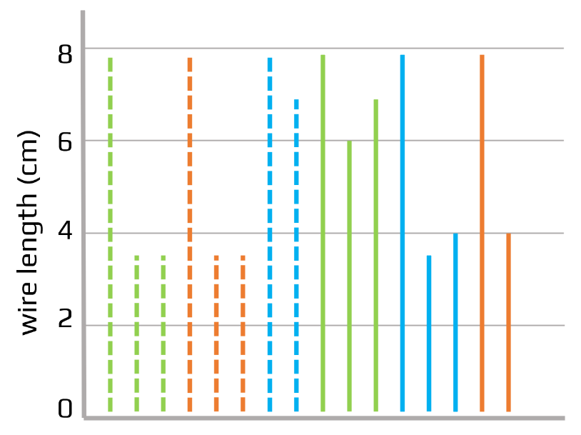
Cut the wires to the correct length
You can use utp cable wiring because it’s color coded. In preparation it is useful to cut the wires to the correct length in advance, and strip them. See the diagram for the approximate lengths.
Solder it
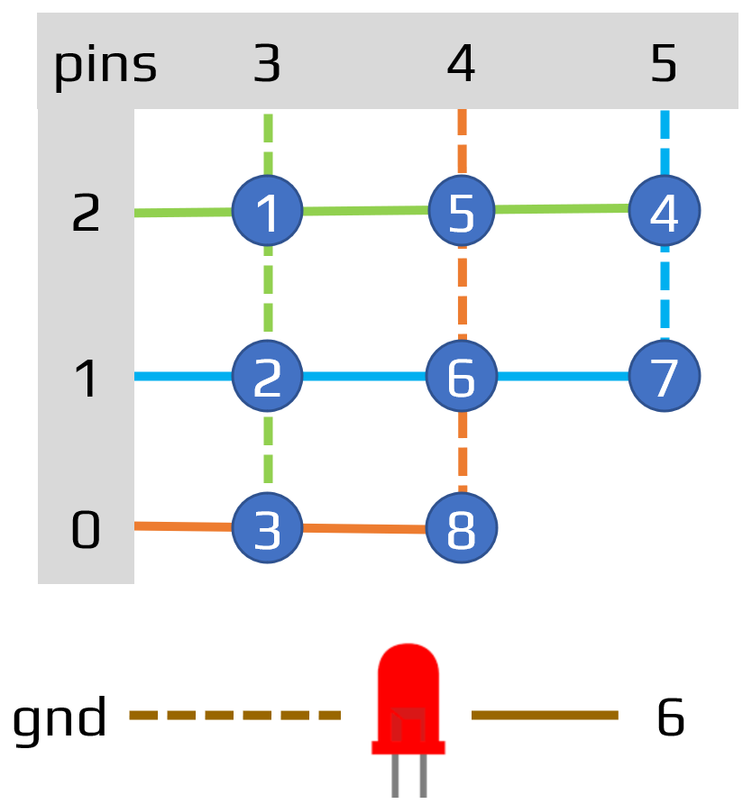
Buttons
The buttons are connected in a keymap configuration to the Arduino. Use the wiring diagram as a guide for connecting the buttons.
Every button has 2 terminals that are shorted if you press the button. Note that most button terminals are connected to 1 or 2 other buttons.
For example: the two terminals of button number 2 have both 2 wires connected:
- One terminal has the dashed green wires: one goes to button 1, the other to a terminal on button 3.
- The other terminal has the blue wires: one goes to the Arduino on pin 1, the other goes to a terminal on button nr 6
The led is connected to gnd and pin 6

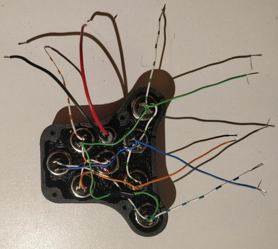
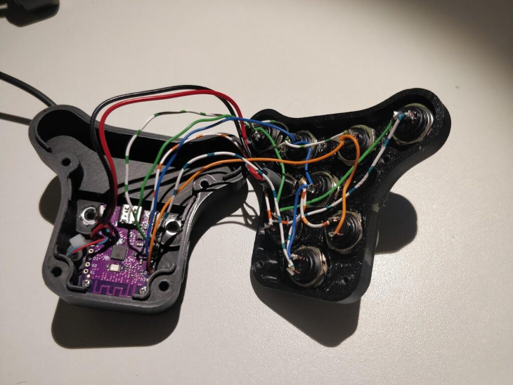
The wires in the front of the case look like this, before assembly to the Arduino board:
Power cable
For power supply you can use a USB cable. The regular charging cables have USB-A on one end and provide 5V DC power. You can use an old or broken one and cut off the micro/mini/usb-c connector:
- Connect the black wire to the gnd pin on the Arduino board (see note below)
- Connect the red wire to the vbus pin on the Arduino board (see note below)
!!! Very important: check the polarity of USB cables before you solder it to the board. Some USB cables have reversed polarity which will brick the Arduino board. !!!
Make sure to route the cable through the housing before soldering. Don’t forget to zip tie the cable from the inside secure it and provide strain relief. Route the USB cable through the hole in the bottom of the back component (nr 2 in the diagram below)
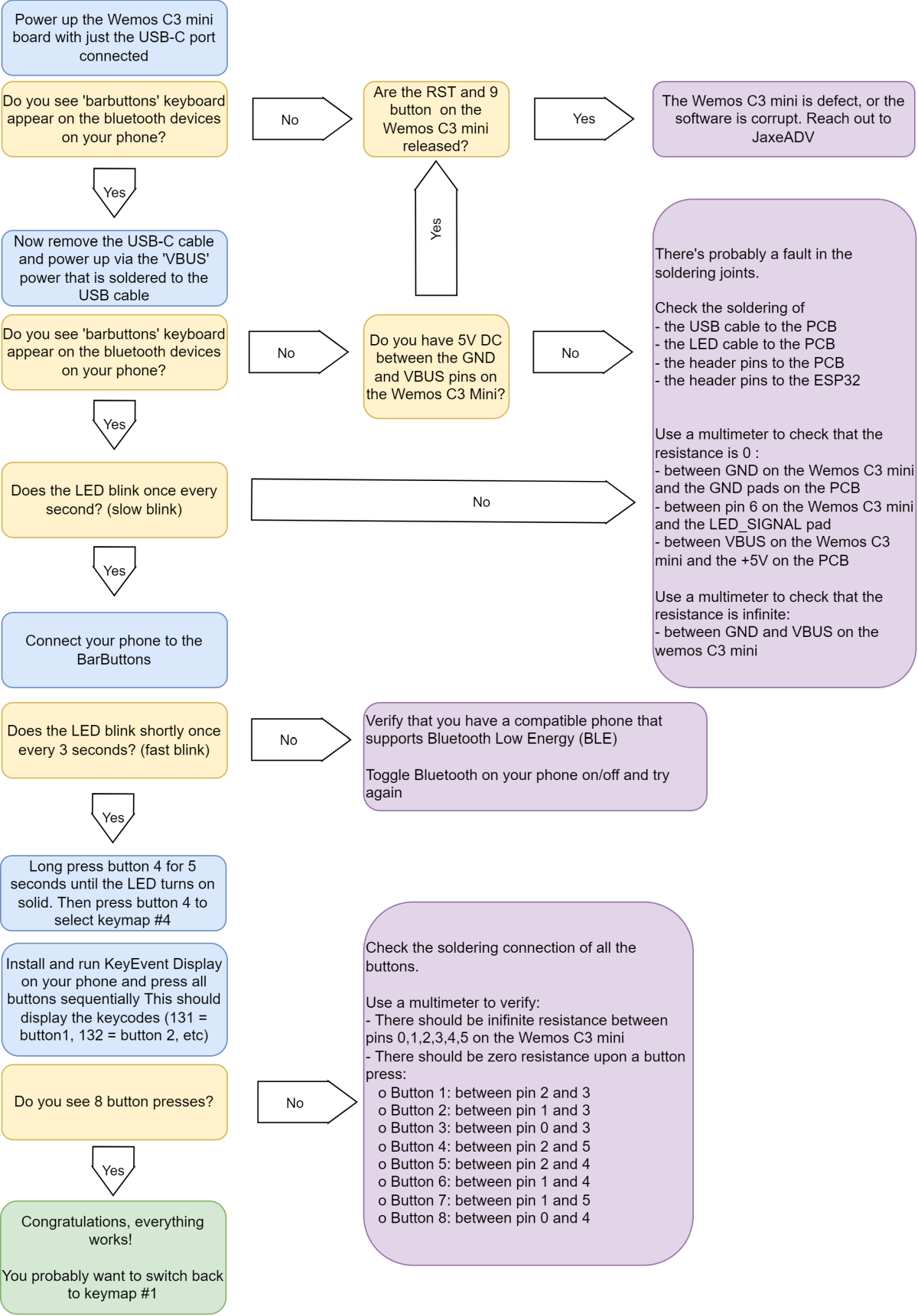
Test it
Use the troubleshooter below to verify everything works as expected:
You can test the pressed keys on the online keytester here: https://jaxeadv.com/barbuttons/keypress-tester/
BarButtons user Teazel has created 2 apps to verify that the keys of the BarButtons are correctly received. You can check them out here:
Assemble it
- Mount the Wemos C3 mini Arduino with 2mm screws of 6mm length (2x) to the inside of the case. (nr 5 in diagram to the right)
- Put 2 m4 nuts in the recesses on the inside of the back part. Press pull them, or heat them slightly with a soldering iron. (nr 4 in diagram to the right)
- Optional: you can use RTV sealant or similar to seal the seating surface to further waterproof the BarButtons (I’ve personally never done this):
- Put the front (with the buttons) on the back, and be careful not to pinch the wires
- Screw in the M3x12 screws and tighten securely (nr 1 in diagram to the right)

Mount it
Now that you have the unit assembled, it’s time to mount it to your handlebars!